Ch 6: CCSM Measures for Central Chiller Plants
The central chiller plant includes chillers, cooling towers, a primary water distribution system and the condenser water distribution system. Although a secondary pumping system may be physically located inside the central plant, commissioning issues dealing with secondary loops are discussed in Chapter 5. The central chiller plant produces chilled water using electricity, steam, hot water or gas. The detailed commissioning measures vary with the type of chiller. This chapter is designed to give the general commissioning measures that apply to a typical central cooling plant that can produce significant energy savings.
6.1 Use the Most Efficient Chillers
Most central chiller plants have several chillers with different performance factors or efficiencies. The differences in performance may be due to the design, performance degradation, age or operational problems. One chiller may have a higher efficiency at a high load ratio while another may have a higher efficiency at a lower load ratio. Running chillers with the highest performance can result in significant energy savings and will also reduce the number of complaints because you will be providing the greatest output for the least input.
The poorer-performing chillers are often older chillers that cannot produce rated capacity and often require more maintenance. However, an old chiller sometimes operates at the manufacturer’s design efficiency, while others will be 20% lower. Measurement of actual chiller performance is very important.
The chiller performance measurement involves measuring chilled water production and energy input. The chilled water production can be determined from measured chilled water flow and supply, and return water temperatures. Flow measurement is extremely important. Do not assume the flow is the design flow if there is a constant speed pump in the chiller primary loop. This should be measured and can be measured accurately and non-intrusively using an ultrasonic meter. To reduce the measurement error, chilled water supply and return water temperatures should be measured using the same sensor. This is a place where a 1°F error in the temperature difference (typically around 10°F) makes an error of approximately 10% in the cooling output determined for the chiller. When existing meters are used, they should be calibrated before the measurement. The power consumption should be determined from a true power measurement instead of using percent of design current as a surrogate for power measurement. The power factor varies significantly as the chiller load changes. The true power fraction is often significantly smaller than the current fraction under partial load. The true power can be measured using an appropriate power meter. The chiller control panel number may be used if it measures true power.
Once the chilled water flow rate, supply, and return chilled water temperatures and chiller electricity consumption have been measured, the kW/ton can be determined using the following formula:
kW/ton = 24kW/[gpm(Treturn – Tsupply)]
Record all other important operating parameters such as condenser supply and return temperatures and flow. When you compare performance of multiple chillers, ensure that the condenser water and chilled water temperatures are similar for all chillers.
For turbine-driven and absorption chillers, the performance is evaluated using the ratio of the tonnage over the heat input. Both heat input and chilled water production should use the same units. The appropriate manual should be consulted for accurate techniques to use for measuring steam and gas energy.
6.2 Reset the Supply Water Temperature
Increasing the chilled water supply temperature can decrease chiller electricity consumption significantly. The general rule-of-thumb is that a one-degree Fahrenheit increase corresponds to a decrease in compressor electricity consumption of 1.7%. The chilled water supply temperature can be reset based on cooling load or ambient conditions.
- Increase the chilled water temperature linearly from the design value up to 5°F (adjustable) higher than the design value as the chiller plant load decreases from 100% to 40%. Or,
- Increase the chilled water temperature from the design value up to 5°F (adjustable) higher than the design value as the ambient temperature decreases from the design value to 60°F. Or,
- Adjust the chilled water temperature within a range of 45°F to 50°F using the valve position. If the maximum open valve in the primary chilled water loop is less than 90-95% open, increase the chilled water supply temperature. If more than one valve is 100% open, decrease the chilled water supply temperature.
- The supply water temperature reset can be implemented using the building or plant automation system (BAS). If it cannot be implemented using the BAS, the operator can reset the set point daily, based on the daily maximum temperature.
Increasing chilled water temperature may increase distribution pump (secondary pump) power consumption. The secondary chilled water flow should be less than 60% of the design flow rate before implementing the chilled water supply temperature reset. Supply temperature reset should not increase it above this level.
The chilled water supply temperature reset directly impacts the dehumidification capability of the coils. The chilled water supply temperature should not be reset to a higher value until the ambient humidity ratio is less than 0.009 or the ambient dew point temperature is less than 57°F for typical facilities.
6.3 Reset Condenser Return Water Temperature
Decreasing cooling tower return water temperature has the same effect as increasing the chilled water supply temperature. The cooling tower return temperature should be reset based on weather conditions. The following provides general guidelines:
- The cooling tower return water temperature set point should be at least 5°F (adjustable according to design) higher than the ambient wet bulb temperature. This prevents excessive cooling tower fan power consumption.
- The cooling tower water return temperature should not be lower than 65°F for chillers made before 1999 and should not be lower than 55°F for newer chillers. It is also recommended you consult the chiller manufacturer’s manual for more information.
The cooling tower return water temperature reset can be implemented using the BAS. If it cannot be implemented using the BAS, operators can reset the set point daily using the daily maximum wet bulb or dry bulb temperature.
Decreasing the cooling tower return temperature may increase fan power consumption. However, fan power may not necessarily increase with lower cooling tower return water temperature. The following tips can help.
- Use all towers. For example, use all three towers when one of the three chillers is used. This may eliminate fan power consumption entirely. The pump power may actually stay the same. Ensure the other two tower pumps are off.
- Never turn on the cooling tower fan before the by-pass valve is completely closed. If the bypass valve is not completely closed, the additional cooling provided by the fan is not needed and will not be used. Save the fan power!
- Balance the water distribution to the towers and within the towers. Water is often seen flowing down only one side of the tower, or one tower may have twice the flow of another. This significantly increases the water return temperature from the towers.
EXAMPLE:
The University of Texas Medical Branch at Galveston has a conditioned area of 3,500,000 ft2. The campus is cooled by a large central plant with seven chillers having a total capacity of 19,400 tons. The plant metering at this site permits trending of major chiller plant operating parameters as shown in Figure 6-1. The figure shows the chiller kW/ton (open rectangle symbols) as a function of the average value of the chilled water supply (open triangle symbols) and return temperatures . When the average chilled water temperature was increased from 42.5°F to 44.5°F, the average kW/ton decreased from approximately 1.02 to approximately 0.90. The average condenser temperature remained at 75°F.
When the average chilled water temperature was increased from 44.5°F to 46°F, the chiller kW/ton increased from 0.9 to approximately 0.95. This increase is due to the increase of the average condenser water temperature. The condenser water temperature increased from 75°F to approximately 89°F. Improving the chilled water and cooling tower water temperature set points can significantly decrease the central plant power consumption.
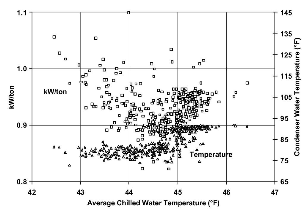
Figure 6-1. Measured Chiller Plant Efficiency and Condenser Water Temperature Plotted as Functions of Average Chilled Water Temperature
Figure 6-2 presents the measured cooling tower return water temperature, improved return water temperature and ambient wet bulb as a function of ambient wet bulb temperature. When the wet bulb temperature is below 60°F, the water is returned from the cooling tower at about 73°F. For higher wet bulb temperatures, the water is about 10°F above the wet bulb temperature. This provided a significant opportunity to improve chiller efficiency by lowering the temperature of the supply water to the condenser to 65°F when the wet bulb is 60°F or below and keeping it approximately 5°F above the wet bulb at higher temperatures.
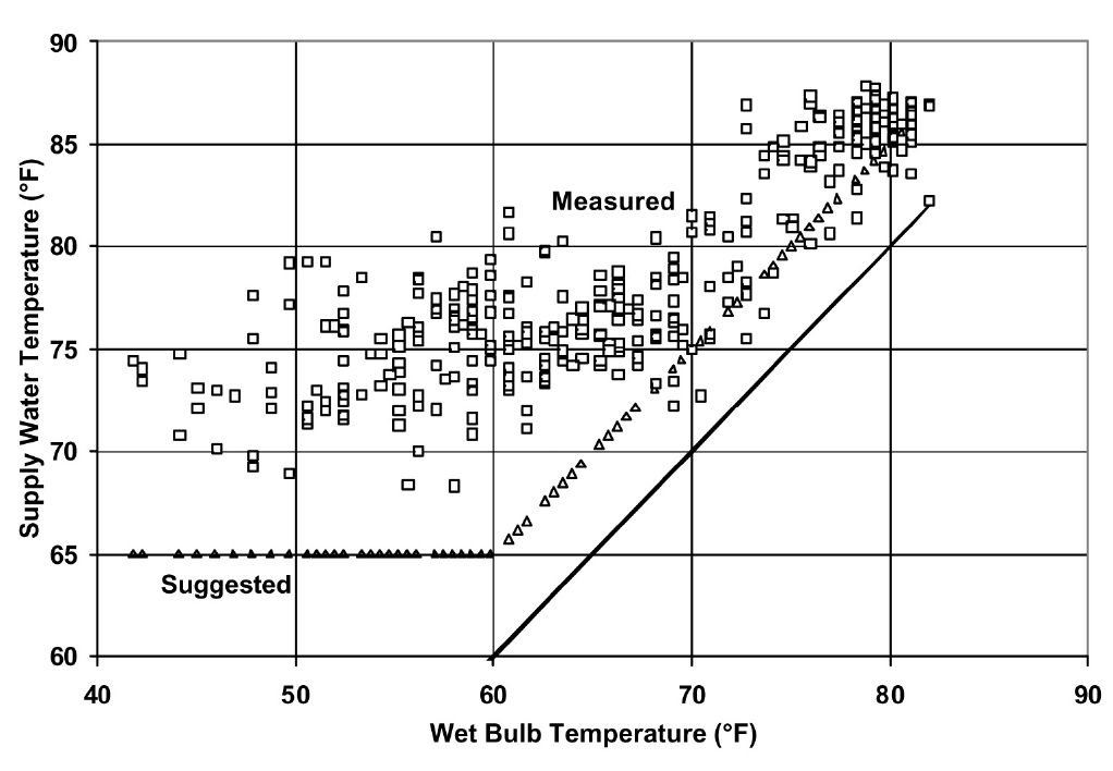
Figure 6-2. Measured Condenser Supply Water Temperature at the UTMB Chiller Plant as a Function of Ambient Wet Bulb Temperature
The measured chilled water supply temperature is shown in Figure 6-3. The plant was operating with a constant supply temperature of about 39°F. The supply temperature schedule suggested for implementation is also shown. It ranges from a high of 45°F when the ambient is about 40°F to a low of 41°F when the ambient is above 85°F.
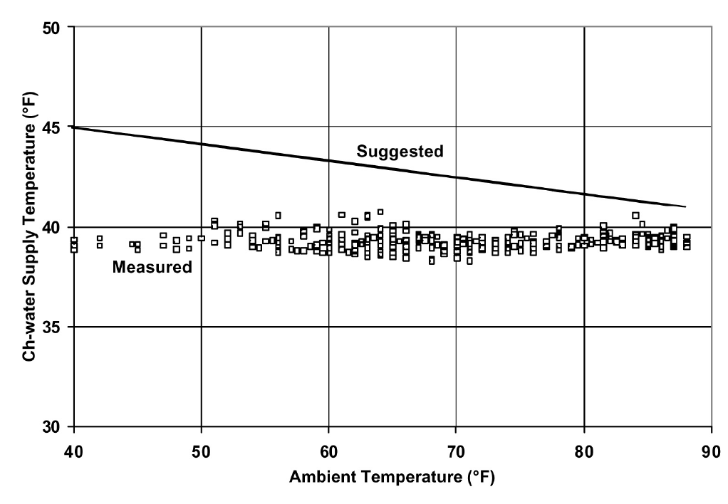
Figure 6-3. Measured And Suggested Chilled Water Supply Temperature at UTMB
The projected savings from implementing the supply temperature reset schedule and changing the cooling tower control was a 22% reduction from 0.92 kW/ton to 0.72 kW/ton on average. The historical plant electrical consumption was 69,711 MkWh which was projected to be reduced to 54,489 MkWh for savings of 15,222 MkWh.
More information can be found in “Use of EMCS Recorded Data to Identify Potential Savings Due to Improved HVAC Operations and Maintenance,” [Liu et al. 1997].
6.4 Increase Chilled Water Return Temperature
Increasing chilled water return temperature has the same effect as increasing chilled water supply temperature. It can also significantly decrease the secondary pump power because the higher the return water temperature (for a given supply temperature), the lower the chilled water flow. The following measures should be used to increase the chilled water return temperature.
- Maximize the chilled water return temperature by closing three-way valves. Three-way valves are often used in existing systems. Under partial load conditions, the chilled water flow rate can be higher than the design flow due to reduced resistance in the valve and coil sections. When a primary/secondary chilled water loop is used or a variable flow loop is used, these three-way valves should be closed. When a single chilled water loop is used, some of the three-way valves can be closed. The number of valves closed depends on the minimum allowable chilled water flow through the chiller.
- Solve existing water balance problems in the buildings to increase the chilled water return temperature
- Optimize the chilled water loop differential pressure set point. In most cases, the differential pressure set point is too high. The control valve often loses control and causes excessively low return water temperature. The optimal pressure set point is discussed in Chapter 5.
Maximizing chilled water return temperature is much more important than optimizing supply water temperature since it often provides much more savings potential. It is difficult to increase supply temperature 5°F above the design set point. It is often easy to increase the return water temperature as much as 7°F by conducting water balancing and shutting off by-pass and three-way valves.
EXAMPLE:
Mclnnis is a university campus building in central Texas. The design differential temperature is 12°F (42/54°F). The building experienced differential temperatures less than 10°F before the water loop balance and building commissioning. During the building commissioning, the chilled water bypass valves were completely closed, and the chilled water loop differential pressure was decreased from 30 psi to a range of 15 psi. Figure 6-4 presents the measured chilled water supply and return water temperatures from the building. The differential temperature was maintained above 15°F after commissioning.
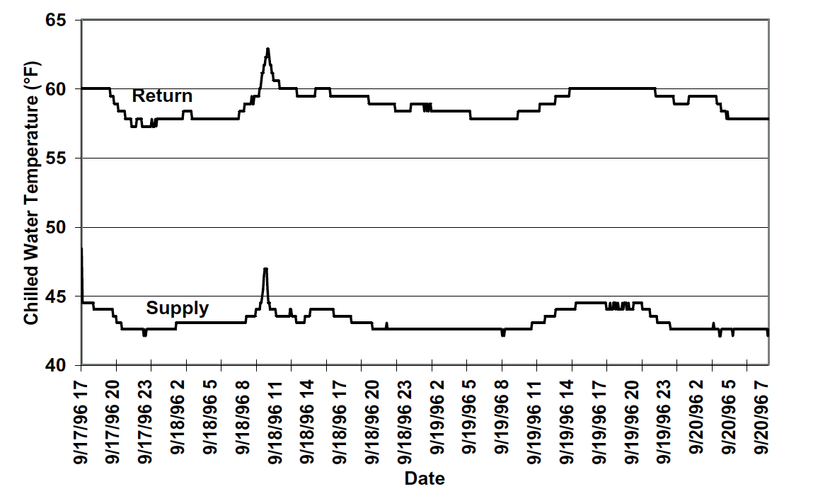
Figure 6-4. Measured Chilled Water Supply and Return Water Temperature After Building Commissioning (the building differential temperature was less than 10°F before commissioning)
6.5 Use Variable Flow under Partial Load Conditions
Typical central plants use primary and secondary loops. A constant speed primary pump is often dedicated to a particular chiller. When the chiller is turned on, the pump is on. Chilled water flow through each chiller is maintained at the design flow rate by this operating schedule. When the building-loop flow is less than the chiller loop flow, part of the chiller flow bypasses the building and returns to the chiller.
This practice causes excessive primary pump power consumption and low entering water temperature to the chiller which increases the compressor power consumption.
It is the general perception that the chilled water flows have to remain constant for chiller operational safety. Actually, most new chillers allow chilled water flow as low as 30% of the design value. The chilled water flow can be decreased as low as 50% for most existing chillers if the following procedures are followed:
- Adjust the flow switch first. The chiller will shut down if the flow switch sends a no-flow signal to the chiller controller. For existing chillers, the flow signal will not be generated until design flow is achieved. Adjust the flow switch and make it send a flow signal as soon as flow reaches 30% of design flow, or more if necessary
- Set a start-up and shut down cycle time of no less than 60 seconds for all pumps and valves. This will prevent sudden water flow changes. This is necessary for old chillers since most controls are very slow.
Varying chilled water flow can be implemented using the following procedures:
- Determine the minimum chilled water flow ratio for each chiller. Vary chilled water flow slowly through the chiller until the chiller shuts down or chilled water flow is reduced to 30% of the design rate. This flow is defined as the minimum flow rate. During the test, the chilled water return temperature should be maintained at the design level; 54°F, for example. The chilled water supply temperature should be set at the design level as well; 42°F, for example. The chilled water flow should be maintained at 30% or higher to prevent deposition of dirt and degradation of heat transfer.
- If the secondary loop flow rate is higher than the minimum flow rate of the chiller(s), close the building bypass valve. Keep the primary pumps on if a VSD is installed on the secondary loop pumps.
- If the secondary loop flow is less than the minimum flow rate of the chiller(s), modulate the bypass valve to maintain the minimum chilled water flow through chillers.
Varying chilled water flow through a chiller can result in significant pump power savings. Although the primary pumps are kept on all the time, the secondary pump power consumption is decreased significantly when compared to the conventional primary and secondary system operation. Figure 6-5 presents the potential pump power savings for a central plant with three identical chillers. If the central plant total load is 60% and the chilled water flow through each chiller is 60%, the primary pump power savings is 78%. If the design pump capacity is 100 kW for each pump, the total pump power savings would be 234 kW. If the central plant has a total load of 40%, two chillers operate at 30% load. The pump power savings ratio is 65%, or 195 kW. If the central plant has a total load of 20%, one chiller is operated at 60%. The pump power savings is 26%, or 78 kW.
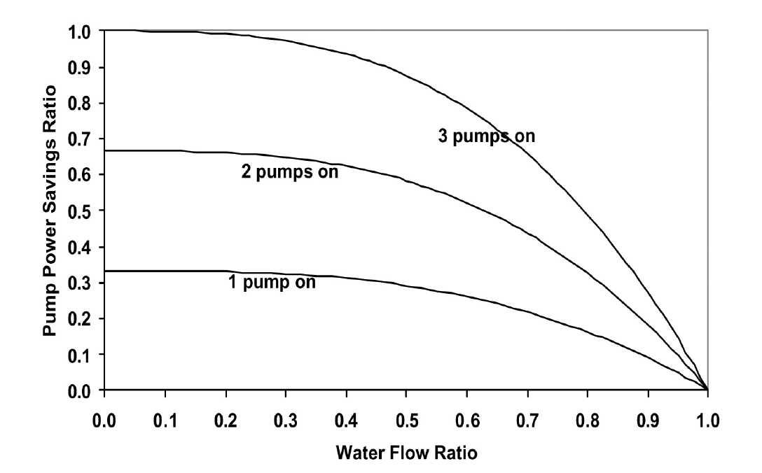
Figure 6-5. Potential Primary Pump Power Savings Ratio Versus Chilled Water Flow Ratio through Each Chiller
Varying chilled water flow through the chillers will also increase the chiller efficiency when compared to constant water flow with chilled water bypass. More information can be found in “Variable Water Flow Pumping for Central Chilled Water Systems” [Liu 2002].
6.6 Optimize Chiller Staging
For most chillers, the kW/ton decreases (COP increases) as the load ratio increases from 40% to 80%. When the load ratio is too low, the capacity modulation device in the chiller lowers the chiller efficiency. When the chiller has a moderate load, the capacity modulation device has reasonable efficiency. The condenser and evaporator are oversized for the load under this condition so the chiller efficiency is higher.
When the chiller is at maximum load, the evaporator and condenser have a smaller load ratio, reducing the chiller efficiency below its maximum value. Running chillers in the high efficiency range can result in significant electrical energy savings and can improve the reliability of plant operation. The optimal chiller staging should be designed using the following procedures:
- Determine and understand the optimal load range for each chiller. This information should be available from the chiller manufacturer. For example, the kW/ton typically has a minimum value when the chiller load varies from 50% to 70% of the design value. However, the chiller system, which includes the chilled water pump and cooling tower fans, may not have the best efficiency when the pump and fans run at full speed.
- Turn on the most efficient chiller first. Optimize the pump and fan operation accordingly.
- Turn on more chillers to maintain the load ratio (chiller load over the design load) within the optimal efficiency range for each chiller. It is assumed that the building bypass is closed.
If the building bypass cannot be closed, the minimum chiller load ratio should be maintained at 50% or higher. In this case, the primary pump power consumption increases with the number of chillers in operation. Although the compressor power is decreased, the primary pump power increases significantly. The total power consumption is often higher if the chiller load is less than 50%.
A single loop may be used for some plants. In this case, a control schedule can be developed to share primary pumps under partial load conditions. For example, when the load is less than 50% for two chillers, a single pump can sometimes be used. If two pumps are used, the central plant may use approximately the same amount of energy as one chiller at peak load.
6.8 Maintain Good Operating Practices
It is important to follow the operating procedures recommended by the manufacturer. It is important to calibrate the temperature, pressure and current sensors and flow switches periodically. The temperature sensors are especially important for maintaining efficient operation. Control parameters must be set properly, particularly the time delay relay.
References
Liu, M., Y. Zhu and D. E. Claridge, 1997. “Use of EMCS Recorded Data to Identify Potential Savings Due to Improved HVAC Operations and Maintenance,” ASHRAE Transactions-Research. Vol. 103, Part 2, pp. 122-129.
Liu, M., 2002. “Variable Water Flow Pumping for Central Chilled Water Systems.” ASME Journal of Solar Energy Engineering, Vol. 124, pp. 300-304.